Appendix: Custom mounting
Glove80 is designed to facilitate custom mounting so that you can mount your Glove80 in countless creative ways.
Here are some of the possibilities:
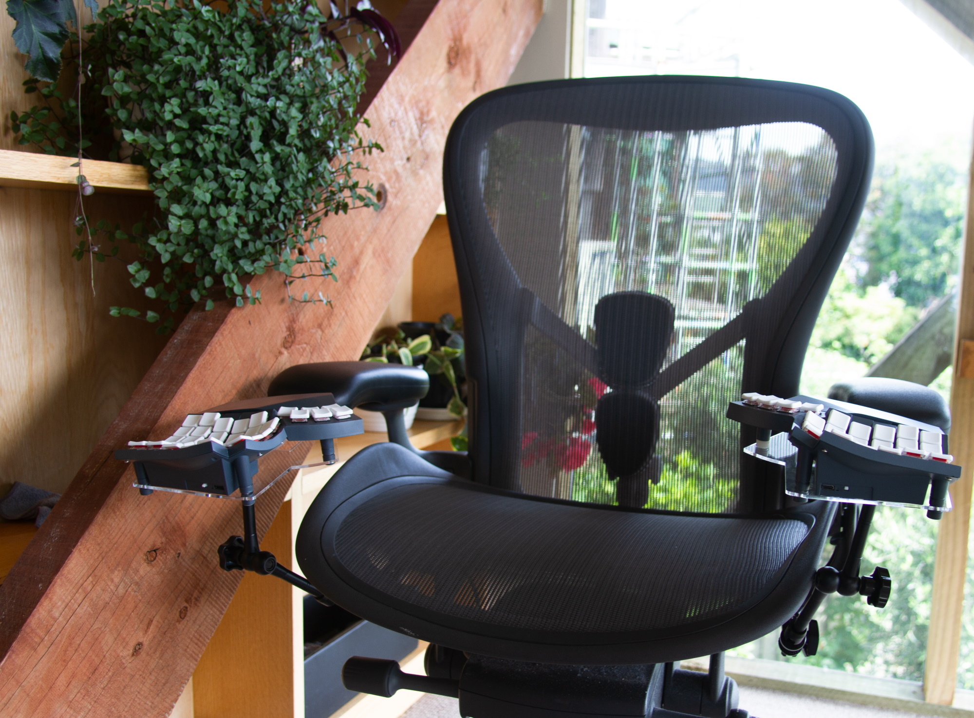
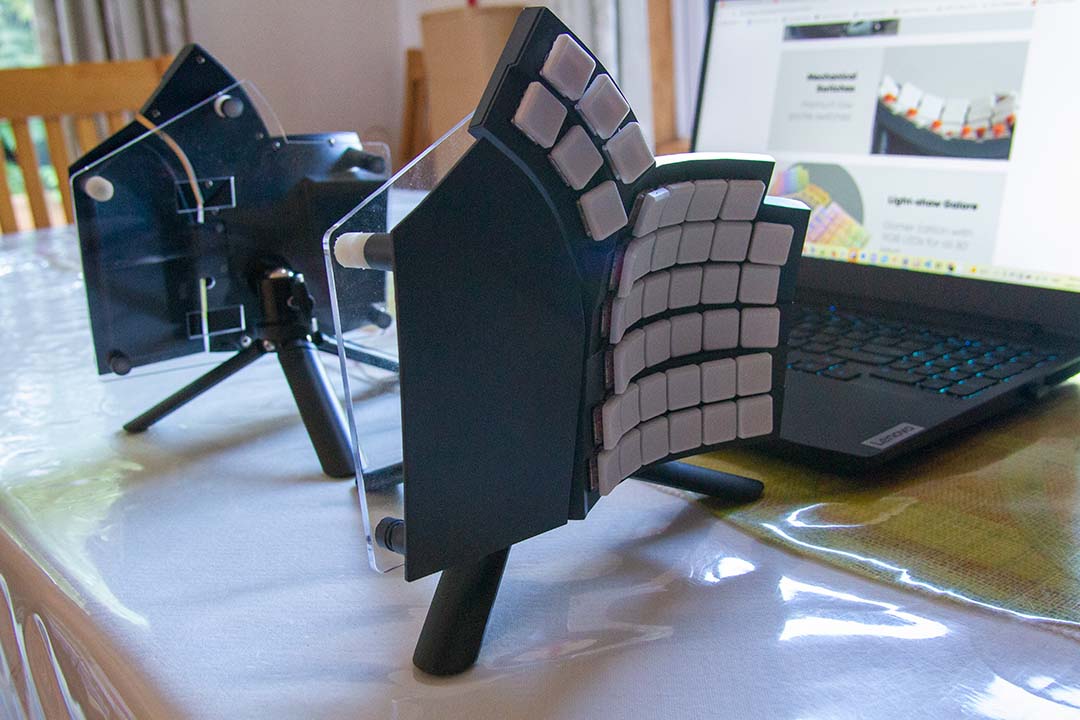
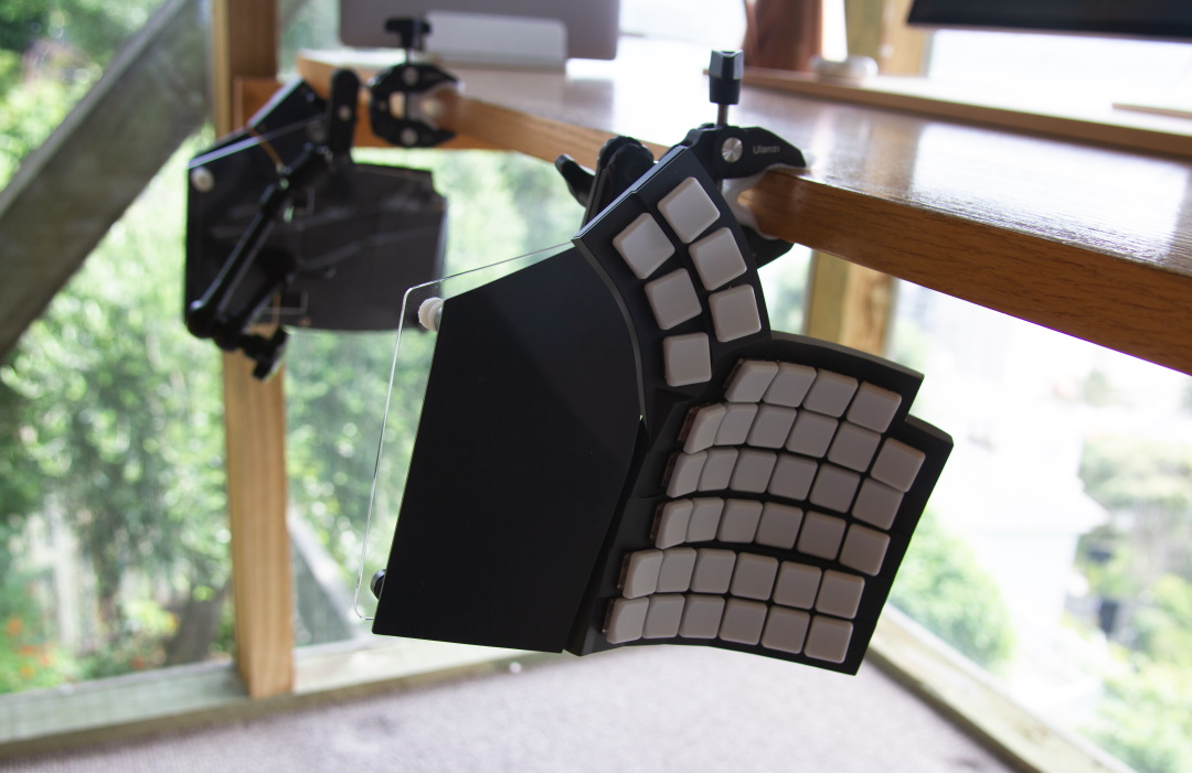
How to custom mount
Procedure:
- For the extensible legs, remove the feet by rotating them to reveal M4 studs.
- For the non-extensible legs, use a craft knife to remove the silicone bumper to reveal an M4 stud.
- Attach M4 threaded rods or M4 screws and use other appropriate fasteners such as nuts to secure Glove80 onto your custom mounting mechanism.
- The additional feet without threaded rods and silicone bumpers included in the Glove80 box are useful as spacers for the extensible legs.
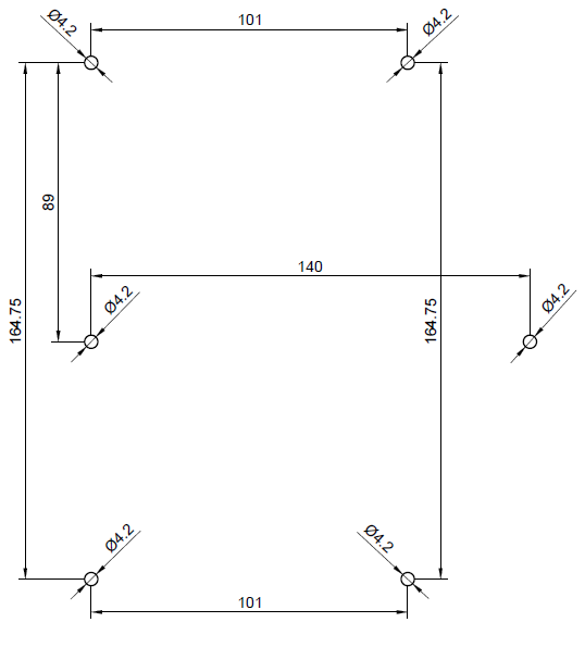
Leg stud positions
Installing tripod mounting plates
MoErgo makes mounting plates available for Glove80 to easily attach to a camera tripod or other mount using the standard tripod mount screws (1/4"-20). They come in three types: V1 quick release or V2 quick release or non-quick release.
A note of the components needed:
- The Glove80 plastic feet without threaded rods attached (either white or grey to match the Glove80 case color) are found in an accessory ziploc bag that comes with Glove80, as well as the accessory ziploc bag that comes with the tripod mounting plates.
- Silicone bumpers are found in an accessory ziploc bag that comes with Glove80
- The threaded rods are found in an accessory ziploc bag that comes with the tripod mounting plates.
To mount the tripod plate onto a Glove80 half:
- Prepare the mounting plates. Please read Preparing the non-quick-release tripod mounting plate or Preparing the v1 quick-release mounting plate or Preparing the V2 quick-release mounting plate, as appropriate for the type of tripod mounting plate you have.
- For the extensible legs, remove the feet by rotating them to reveal M4 studs. Remember the original locations. Do not mix.
- For the fixed leg, use a craft knife to remove the silicone bumper to reveal an M4 stud. Do not throw away this silicone bumper; please wrap it in wax paper or Glad wrap for safekeeping. Mark it as “Silicone bumper for Glove80 fixed leg” in case you need to use it again in the future. This silicone bumper is different from the others.
- Turn the keyboard half upside down.
- For the palm rest short leg, add a foot without a silicone bumper, as a spacer, then screw in a 20mm threaded rod through the spacer into the M4 stud in the palm rest.
- For the C6R1 leg (under F1 and F10 in the default layout), add a foot without a silicone bumper, as a spacer, then screw in a 25mm threaded rod through the spacer into the M4 stud in the leg.
- Position a foot without a threaded rod, to act as a spacer, for each extensible leg (other than the palm rest short leg and the C6R1 leg).
- Put the tripod mounting plate over the up-turned half, lining up the holes in the tripod mounting plate with the legs.
- For all feet removed in step 2 (other than the one for the palm rest short leg, and the one in C6R1 position) screw the feet through the spacer foot into the M4 studs in the same leg. Tighten each foot against the acrylic plate until finger-tight; don’t overtighten.
- For the fixed leg, use the foot removed from the palm rest short leg in step 2, and screw the foot into the M4 stud. Tighten the foot against the acrylic plate until finger-tight; don’t overtighten.
- For the palm rest short leg and the C6R1 leg, then screw another foot without a threaded rod on top of the acrylic plate through the threaded rod installed in step 6 or 7. Then apply a silicone bumper from the accessories bag that comes with Glove80. Tighten the foot against the acrylic plate until finger-tight; don’t overtighten to result in bending of the acrylic plate.
- Now tighten all spacer feet tight against the acrylic plate.
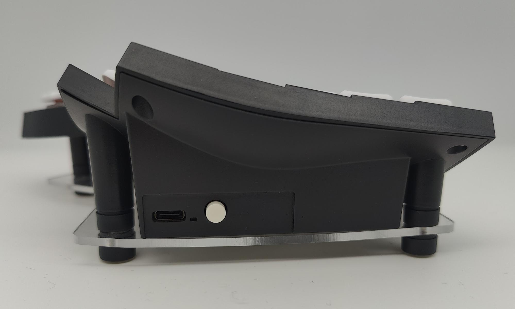
The finished product should look like:
Preparing the non-quick-release tripod mounting plate
- Peel off the protection sheets from the 2 tripod plates. The protection sheets are the brown layer on both sides of the acrylic plates for protecting against scratches during transport.
- Attach your tripod gear through the hole in the middle of the tripod mounting plate.
- Secure your tripod gear to the tripod mounting plate by installing and securing the tripod nut in the Tripod Mounting Plate Accessories Bag.
Preparing the V1 quick-release mounting plate
- Peel off the protection sheets from the 2 tripod plates. The protection sheets are the brown layer on both sides of the acrylic plates for protecting against scratches during transport.
- Take out the two quick release ball joints from the cardboard boxes
- Peel off the double-sided tape on each of the two quick release ball joints
- Attach a quick release ball joint to the rectangular trough in the middle of a mounting plate, lining up the rim of the quick release ball joint with the trough.
- Screw tight the tripod nut in the Tripod Mounting Plate Accessories Bag to secure the quick release ball joint.
Preparing the V2 quick-release mounting plate
- Remove the two acrylic plates from the protective packing material. They are already pre-assembled, and ready for the rest of the installation process.