Appendix: Glove80 with switches-not-soldered option
Danger
For Glove80 with switches-not-soldered option, GLOVE80 WARRANTY DOES NOT COVER ISSUES RELATED TO THE SOLDERING QUALITY OF THE KEY SWITCHES, NOR DAMAGES THAT OCCUR DURING OR AS A RESULT OF THE DISASSEMBLY, SOLDERING, AND REASSEMBLY PROCESS. Glove80 with the switches-not-soldered option are for customers with suitable electronics and soldering skills and equipment.
Replacing and soldering key switches
- Make sure you are suitably grounded with a ground strap.
Danger
Electronics are sensitive to electric shock, which can result in immediate or delayed damage. Please make sure you are suitably grounded before opening the case of Glove80.
- Removing the 8 case screws that hold together the case of each half, with a suitable screwdriver.
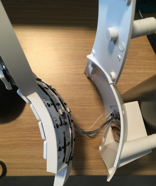
- While opening the keyboard case, be very careful and slow. You will find that there are 4 FFC cables attached to the finger PCBs in the upper shell to the controller PCB in the lower shell.

- Detach the 4 FFC cables by opening each of the 4 FFC connectors on the finger PCBs. To open the FFC connector, lift its black tab away from the FFC cable end like lifting a car bonnet.
- Now you can separate the upper shell and the lower shell.
-
If you would like to replace the key switches,
- Remove only one key switch, by pushing from the inside of the shell on the 3 black plastic legs.
Warning
Do not remove more than one key switch at a time from the Glove80. Removing multiple key switches will make it likely for the finger PCB(s) to disengage from the case. Without suitable knowledge and experience, it is possible to damage the electronic components when reinstalling the finger PCB back into the case.
- Install a suitable replacement Choc v1 key switch. Visually inspect that the key switch is sitting flat on the case, and that the two electrical pins are through the PCB.
- Solder the pins of each key switch to a high quality. Please ensure that the soldering temperature and duration complies with the Kailh Choc v1 datasheets (https://www.kailhswitch.com/mechanical-keyboard-switches/low-profile-key-switches/linear-mechanical-keyboard-switches.html).
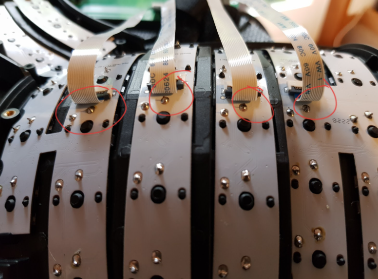
- On each side of the keyboard, please use a plier and clip short the key switch legs circled in the photo below. This step is essential for preventing damage to FFC cables.

Note
The photo is shown with FFC cables attached, to demonstrate the risk of damage to the FFC cables if these switch legs are not clipped
- Reconnect the 4 FFC cables.
- Close the case shell and install the case screws.